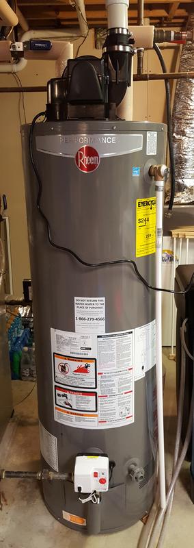
Rheem Power Vent Water Heater 42vp50fw Manual
Professional Classic Series: Power Vent. 0.65 UEF (0.67 EF) Induced draft with the Guardian FVIR System; Flexible venting options up to 100 feet; 40, 50 and 60 gallon capacities.
- We have 2 Rheem PowerVent Commercial Gas Water Heater manuals available for free PDF download: Use & Care Manual, Datasheet Rheem PowerVent Commercial Gas Water Heater Use & Care Manual (36 pages) Residential Gas 75 Gallon.
- Manuals and free instruction guides. Find the user manual.

- Look for the Genuine Factory Authorized seal on heater kits and other accessories.
- Why? Because there is no substitute for the quality and performance of original factory equipment that is verified by UL and CSA to meet published OEM specifications.
- Only PROTECH heater kits and PROTECH accessories full satisfy Rheem Manufacturing Company's performance standards and are certified and warranted by Rheem.
The PROTECH Master Catalog is your source for quality HVAC products and parts! Find pictures and descriptions of more than 6,000 professional HVAC parts, supplies and accessories that are stocked and ready to ship. The PROTECH Master Catalog is also a complete reference for authorized replacement parts to Rheem, Ruud and WeatherKing air conditioning and heating equipment. There is no need to go anywhere else for your professional HVAC and water heater parts, supplies and accessories. A reader-friendly product categories feature makes locating product easy and convenient.
The parts in this catalog are available from authorized Rheem dealers and distributors. The information in this catalog is not intended for part selection purposes when making repairs to original equipment. Refer to the appropriate unit parts list when selecting replacement parts. Rheem does not warrant the suitability of the parts in specific applications, nor does it warrant the accuracy of information provided by the manufacturers of the components and accessories that appear in this catalog. The installing/servicing contractor should verify the suitability of the parts and/or accessories listed in this catalog, and confirm the proper and safe operation of equipment after parts installation.
Web Catalog Show All Categories
|
|
|
|
|
|
10018
®
SYSTEM SENTINEL
POWER
THERMOSTAT
IGNITION
PILOT VALVE
MAIN VALVE
ECO
“System Sentinel” Diagnostic System
The “System Sentinel” Diagnostic system on this water heater provides the user or service technician with a visual representation of the
operational status of the various sections of the water heater’s control system. A quick glance at the System Sentinel panel on the front of
the heater will give an indication of where to begin trouble shooting of a non operational heater.
The LED’s (light emitting diodes) on the panel are arranged from top to bottom based on their function in the normal sequence of operation,
and their function is explained as follows:
POWER

When illuminated, this green LED indicates that 120VAC power is
being supplied to the heater, the ON/OFF switch is functioning and
the 24V transformer is functioning properly.
(Refer to Section 1 of Troubleshooting Guide)
THERMOSTAT
When illuminated, this red LED indicates that the ther-
mostat is functioning(calling for heat) and 24VAC power
is being supplied to the relay (to turn on the blower) and
the N/C terminal of the pressure switch with N/C and N/O
terminals.
(Refer to Section 2 of Troubleshooting Guide)
IGNITION
When illuminated, this red LED indicates that 24 VAC
power is being supplied to the Ignition Control Module,
and the ignition sequence has begun. The N/O side of the
pressure switch with N/C and N/O terminals closes
(Refer to Section 3 of Troubleshooting Guide)
PILOT VALVE
When illuminated, this red LED indicates that the Ignition
Control Module is supplying 24 VAC power to the ECO
(Energy Cut Off device), or High Limit.
(Refer to Section 4 of Troubleshooting Guide)
ECO
When illuminated, this red LED indicates that the ECO
(Energy Cut Off device), or High Limit is closed, and 24
VAC power is being supplied to the PV (Pilot Valve) ter-
minal on the Gas Control Valve.
(Refer to Section 5 of Troubleshooting Guide)
Rheem Power Vent Water Heater 42vp50fw Manual
MAIN VALVE
When illuminated, this red LED indicates that the Ignition Control
Module is supplying 24 VAC power to the MV (Main Valve) terminal
on the Gas Control Valve.
(Refer to Section 6 of Troubleshooting Guide)